
IR Remote Control Reverse Engineering
What if you'd like to control your HiFi with your smartphone, but it lacks the needed interface? One solution could be to emulate your ir-remote with an Arduino.
That's what I did with my Onkyo TX-SR309.
First hook an oscilloscope to the IR diode of your remote control and try to measure the carrier frequency. Most likely this will be a 38KHz signal.
I use a DSO-203 even though it has bugs, it is very suitible for that kind of work. If the trigger is configured correctly and VOLTS/DIV and TIME/DIV are set properly, you should see an image similar to one of the screenshots below.
Reverse Engineering Procedure
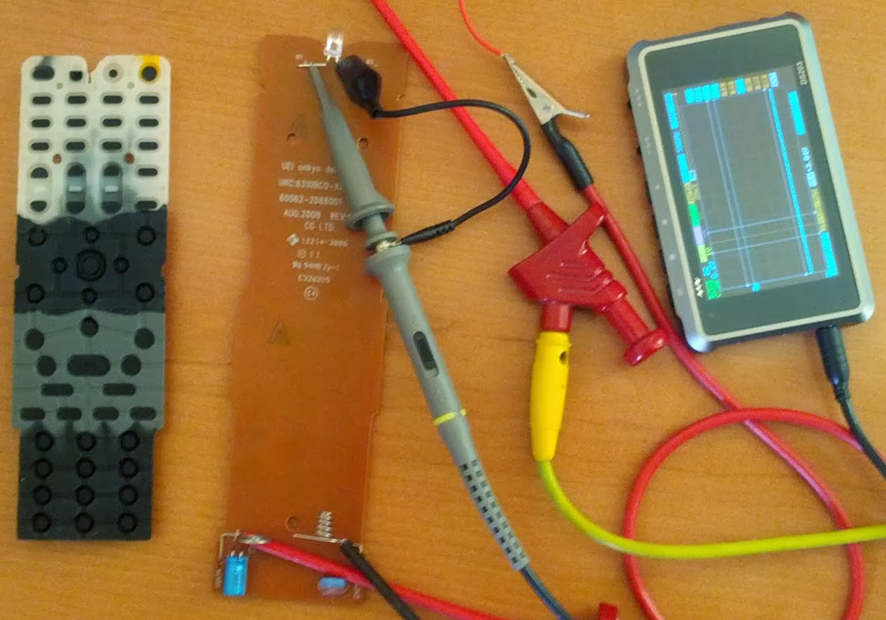 I found measuring directly on the diode simpler then building a ir-receiver,
even though one has to take apart the remote control.
I found measuring directly on the diode simpler then building a ir-receiver,
even though one has to take apart the remote control.
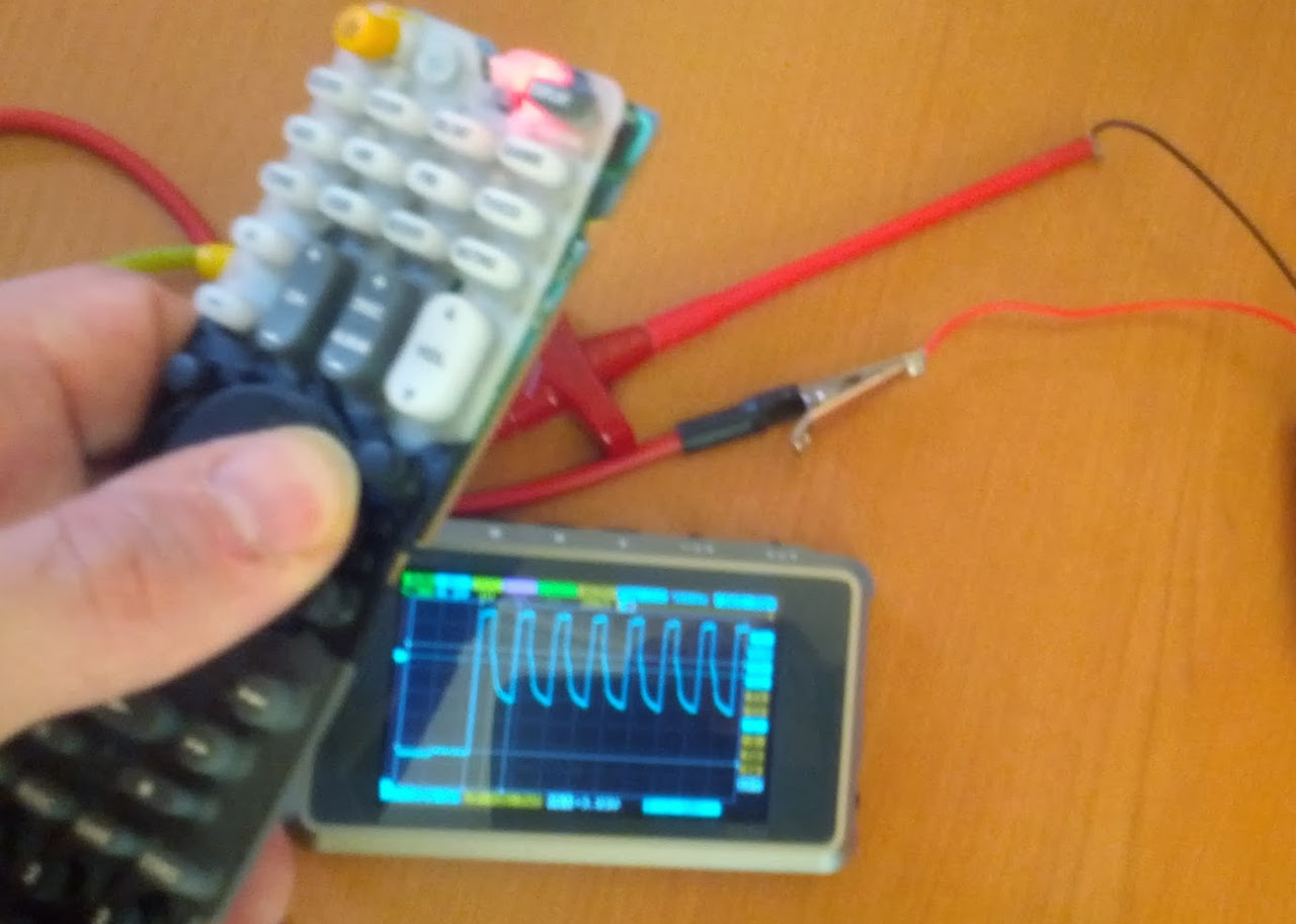 Now we have to press each button on the remote and write down the bits as they
are sent.
Now we have to press each button on the remote and write down the bits as they
are sent.
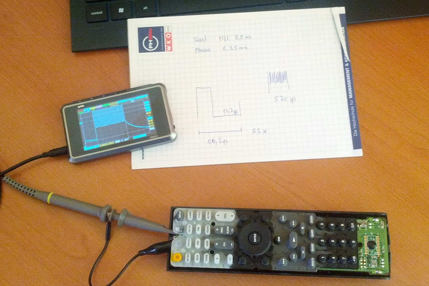 The first measurements already show some repeating patterns, e.g. start pulse
and remote ID are always the same.
The first measurements already show some repeating patterns, e.g. start pulse
and remote ID are always the same.
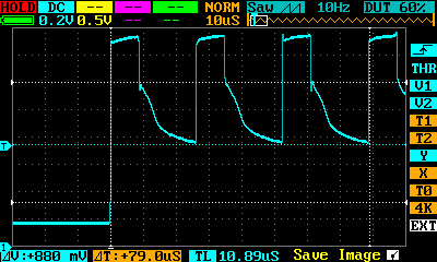 This is the 38KHz carrier frequency. 3 pulses take 79μs so we calculate
1÷(79÷3×10^-6=37974.68Hz≈38KHz.
This is the 38KHz carrier frequency. 3 pulses take 79μs so we calculate
1÷(79÷3×10^-6=37974.68Hz≈38KHz.
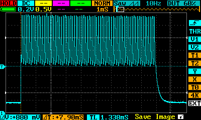 The start of one transmission is marked by a 9ms pulse. This is like the start-
bit in RS232.
The start of one transmission is marked by a 9ms pulse. This is like the start-
bit in RS232.
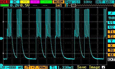 Here, actual bits are transmitted, i.e. the byte 01001011 (last 1 not shown
completely). This happens to be the ID of the remote sent on every button press.
Here, actual bits are transmitted, i.e. the byte 01001011 (last 1 not shown
completely). This happens to be the ID of the remote sent on every button press.
Onkyo RC-799M Protocol
Timings
-------

T=580μs

0 ... 1T high 1T low
1 ... 1T high 3T low

Protocol
--------

Start ... 16T high 8T low

power:        01001011 00110110 11010011 00101100 x
display:      01001011 00110110 10101010 01010101 x

bd/dvd:       01001011 00110110 00110001 11001110 x
vcr/vdr:      01001011 10110110 11110000 00001111 x
cbl/sat:      01001011 10110110 01110000 10001111 x
game:         01001011 10110110 10110000 01001111 x
aux:          01001011 10110110 11111001 00000110 x
am:           01001011 10110110 11100010 00011101 x
fm:           01001011 10110110 10010000 01101111 x
tv/cd:        01001011 10110110 10010000 01101111 x
tone:         01001011 00110110 10010010 01101101 x
usb:          01001011 00110101 01111001 10000110 x
mute:         01001011 10110110 10100000 01011111 x

plus:         01001011 00110110 00000010 11111101 x
minus:        01001011 00110110 10000010 01111101 x
channel up:   01001011 10110110 00000000 11111111 x
channel down: 01001011 10110110 10000000 01111111 x
volum up:     01001011 10110110 01000000 10111111 x
volum down:   01001011 10110110 11000000 00111111 x

sp a/b:       01001011 00110110 00010001 11101110 x
setup:        01001011 00110110 11001010 00110101 x
home:         01001011 10011000 00000011 11111100 x
return:       01001011 00110110 00101010 11010101 x
up:           01001011 10110110 01000001 10111110 x
down:         01001011 10110110 11000001 00111110 x
left:         01001011 10110110 00100001 11011110 x
right:        01001011 10110110 10100001 01011110 x
enter:        01001011 10110110 11101001 00010110 x

|<<:          01001011 00110100 01111000 10000111 x
>>|:          01001011 00110100 10111000 01000111 x
<<:           01001011 00110100 10000000 01111111 x
>:            01001011 00110100 11011000 00100111 x
>>:           01001011 00110100 00000000 11111111 x
||:           01001011 00110100 11111000 00000111 x
[]:           01001011 00110100 00111000 11000111 x

movie/tv:     01001011 00110110 00010001 11101110 x
music:        01001011 00110110 10001001 01110110 x
game:         01001011 00110110 10001011 01110100 x
stereo:       01001011 00110110 00110010 11001101 x

1:            01001011 01000000 10101011 01010100 x
2:            01001011 01000000 01101011 10010100 x
3:            01001011 01000000 11101011 00010100 x
4:            01001011 01000000 00011011 11100100 x
5:            01001011 01000000 10011011 01100100 x
6:            01001011 01000000 01011011 10100100 x
7:            01001011 01000000 11011011 00100100 x
8:            01001011 01000000 00111011 11000100 x
9:            01001011 01000000 10111011 01000100 x
0:            01001011 01000000 01111011 10000100 x
+10:          01001011 01000000 00001011 11110100 x
clr:          01001011 01000000 10001011 01110100 x

Stop ... 1T high

Key Repeat
----------

When a key is held down, there is a gap of 38.5ms before the next key event is
sent.
There are two things that imediately catch our attention here. First the first byte transmitted is always 01001011, obviously the remote controller ID and second the last byte is always the same as the third one but inverted. Now we have all we need to write a sketch to emulate the ir-remote.
The following sketch does exactly that. It listens for commands on the serial interface and sends the correct pulses on pin 11. The bits from the protocol specification have to be reversed (MSB first to LSB first) and converted to hex (see example code below). Keep in mind that measured times differe from actual times in the code due to function call overheads.
Arduino Onkyo RC-799M Emu
// ---------------------------------------------------------------------
// IR class (Onkyo RC-799M)
// ---------------------------------------------------------------------

#define RED_LED_PIN     13
#define IR_LED_PIN      11

#define TIME_BASE      580  // calc: 579us, measure: 583us

#define PULSE_HIGH       3  // 9μs
#define PULSE_LOW        9  // 17μs

#define DEVICE_ID     0xD2  // reverse of 01001011 in hex


class IR {

private:

  // Send a 38kHz-modulated pulse
  static void
  Pulse(void) {
    for (byte i=0; i<22; i++) {
      digitalWrite(IR_LED_PIN, HIGH);
      delayMicroseconds(PULSE_HIGH);
      digitalWrite(IR_LED_PIN, LOW);
      delayMicroseconds(PULSE_LOW);
    }
  }

  // Send a bit
  static void
  SendBit(byte b) {
    Pulse();

    if (b) {
      delayMicroseconds(TIME_BASE * 3); // one
    } else {
      delayMicroseconds(TIME_BASE * 1); // zero
    }
  }

  // Send a byte
  static void
  SendByte(byte b) {
    for (byte i=0; i<8; i++) SendBit((b>>i) & 0x01);
  }

public:

  static void
  SendCommand(byte device, byte byte1, byte byte2, byte byte3) {
    cli(); // disable interrupts

    // start transmission
    for (byte i=0; i<16; i++) Pulse();
    delayMicroseconds(TIME_BASE * 8);

    // send data
    SendByte(device);
    SendByte(byte1);
    SendByte(byte2);
    SendByte(byte3);

    // stop bit
    Pulse();

    sei(); // enable interrupts
  }
};


// ---------------------------------------------------------------------
// Initialization
// ---------------------------------------------------------------------

String input = "";         // a string to hold incoming data
boolean process = false;   // whether the string is complete

void
setup() {
  // Onboard Led
  pinMode(RED_LED_PIN, OUTPUT);
  digitalWrite(RED_LED_PIN, LOW);

  // IR Led
  pinMode(IR_LED_PIN, OUTPUT);
  digitalWrite(IR_LED_PIN, LOW);

  // Serial Console
  Serial.begin(19200);

  // reserve 20 bytes for the inputString:
  input.reserve(20);
}

// ---------------------------------------------------------------------
// Main Program
// ---------------------------------------------------------------------

void
loop() {
  if (process) {
    byte byte0 = DEVICE_ID, byte1 = 0x00, byte2 = 0x00;

    if (input == "status") {
      Serial.println("OK");
    } else if (input == "mute") {
      byte1 = 0x6D; byte2 = 0x05;
    } else if (input == "vol+") {
      byte1 = 0x6D; byte2 = 0x02;
    } else if (input == "vol-") {
      byte1 = 0x6D; byte2 = 0x03;
    } else if (input == "ps2") {
      byte1 = 0x6D; byte2 = 0x0D;
    } else if (input == "xbmc") {
      byte1 = 0x6C; byte2 = 0x8C;
    } else if (input == "power") {
      byte1 = 0x6C; byte2 = 0xCB;
    } else if (input == "speaker") {
      byte1 = 0x6C; byte2 = 0x88;
    } else if (input == "movie") {
      byte1 = 0x6C; byte2 = 0x53;
    } else if (input == "music") {
      byte1 = 0x6C; byte2 = 0x91;
    } else if (input == "game") {
      byte1 = 0x6C; byte2 = 0xD1;
    } else if (input == "stereo") {
      byte1 = 0x6C; byte2 = 0x4C;
    } else {
       Serial.println("?");
    }

    if (byte1 != 0x00) {
      digitalWrite(RED_LED_PIN, HIGH);
      IR::SendCommand(byte0, byte1, byte2, ~byte2);
      digitalWrite(RED_LED_PIN, LOW);
      Serial.println("!");

      delay(38); // minimum delay before next key can be sent
    }

    input = "";
    process = false;
  }
}

void
serialEvent() {
  while (Serial.available()) {
    char c = (char)Serial.read();

    if (c == '\n') {
      process = true;
    } else {
      input += c;
    }
  }
}
Now we are ready to test the sketch on actual hardware. An Arduino Mega was the closest to me at that time of day, so that's what I used. I ripped out the ir- diode from an old remote control, soldered it to two resistors (2x330Ohm in parallel -> 165Ohm) and was ready to go.
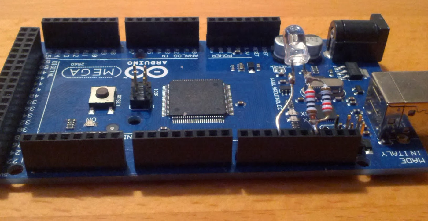 With only a resistance 165Ohm we push the pin to it's limits, but I wanted the
diode to be as bright as possible.
With only a resistance 165Ohm we push the pin to it's limits, but I wanted the
diode to be as bright as possible.
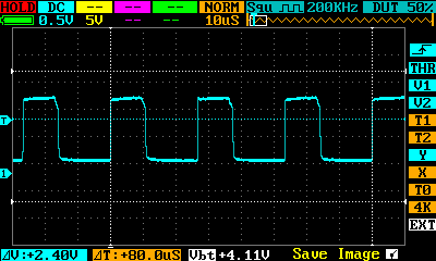 After everything is connected, we can use the same test method to check the
output signal of the Arduino.
After everything is connected, we can use the same test method to check the
output signal of the Arduino.
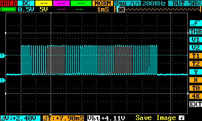 Compared to the original signal we have a perfect match of pulse width and pulse
pause.
Compared to the original signal we have a perfect match of pulse width and pulse
pause.
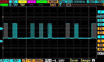 Not really surprising - the signal shape (rectangle) from the emulation is even
better then the original.
Not really surprising - the signal shape (rectangle) from the emulation is even
better then the original.